Generates a dynamic map image from a data frame (map) in an ArcGIS Server map service.
ExportMapImage(MapDescription MapDescription, ImageDescription ImageDescription)
|
Parameter |
Description |
|
MapDescription |
Used to define the contents and extent of the map image, such as layer visibility and extent. |
|
ImageDescription |
Used to define the physical properties of the map image, such as height and width in pixels and image output type. |
Return Value
A MapImage referencing the properties of the generated map image such as image width and height, map extent, map scale, and dpi. The MapImage also maintains a set of properties to store the URL of the generated map image or the MIME data stream of the image contents.
Remarks
ExportMapImage is designed to maintain
aspect ratio, so the map extent provided as part of the MapDescription may be different
than the map extent in the generated map image. To get the map extent
of the generated image, use the MapImage.Extent
property. Further modifications to the MapDescription and ImageDescription input parameters
to alter map image content are discussed below:
MapDescription
The default MapDescription
for a data frame contains the default description properties for a map
it will generate. This can be retrieved via the MapServerInfo.DefaultMapDescription
property. This object can be modified to change contents and properties
of the generated map image. A number of modifications can be implemented:
Change layer visibility
The LayerDescriptions property
of the MapDescription
returns an array or LayerDescription
objects, one for each layer in the data frame in a map service. The LayerDescription.Visible property can be set to true
or false to change layer visibility. Note that LayerDescription includes a reference
to the unique layer id (via the LayerID
property), but not layer name. Use the MapLayerInfo array from the MapServerInfo's
MapLayerInfos property to associated
layer id and name.
Define map extent
Set the MapDescription.MapArea.Extent property to an instance of EnvelopeN. This envelope can be created from scratch and define minimum and maximum x and y values. Note that the aspect ratio of the generated map image will be maintained so the extent of the output MapImage may differ from the extent defined as part of the input MapDescription.
Define spatial reference
Data frame contents
can be projected on the fly. The spatial reference of two items must be
known: the map and the extent envelope. The MapDescription's SpatialReference
property defines the coordinate system of the output map image. The EnvelopeN.SpatialReference property on the extent
envelope defines the coordinate system of the requested extent. They do
not need to match. The extent envelope will be projected from its coordinate
system into the map coordinate system by the map service.
The ProjectedCoordinateSystem
and GeographicCoordinateSystem
classes both implement SpatialReference.
To define a spatial reference you can use a well-known id or a projection
string. The well-known id is defined using the SpatialReference.WKID property.
Note, to use a well-known id, the SpatialReference.WKIDSpecified
property must be set to true. A projection string can be defined via the
SpatialReference.WKT property.
Set transparent background color
To overlay multiple
maps, it may be beneficial to generate a map image in which the background
color is transparent. MapDescription
maintains two properties of interest for this situation. MapDescription.TransparentColor
defines the single color to render transparent. MapDescription.BackgroundSymbol.Color stores a reference to the current
background color. If they are the same, the background in the map image
will be transparent. The image type must also support transparency. For
example, PNG and GIF support transparency but JPEG does not.
Add graphics
Custom graphics can be added to a map image via the MapDescription.CustomGraphics property which stores an array of GraphicElement objects. A GraphicElement consists of geometry and a symbol. The symbol type should be valid for the geometry type. For example, geometry of type PointN must be rendered using a type of MarkerSymbol.
ImageDescription
ImageDescription is used to define
raw image properties. It is composed to two properties: ImageType and ImageDisplay.
ImageType defines the image type and method for returning the image
content. Supported image types are 'bmp', 'jpg', 'tif', 'png'/'png8',
'png24', 'emf', 'ps', 'pdf', 'ai', 'gif', and 'svg'/'svgz'. Image content
can be returned as a URL or as a MIME data stream.
ImageDisplay
defines the height, width and DPI of the image. Note that the DPI is merely
used by the map service to determine map scale on the server, it does
not define the resolution of the map image. In this case, map scale is
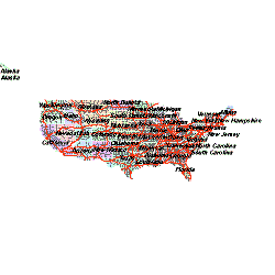
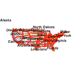
used to determine how to render scale dependent symbols and layers. For
example, both map images included below were generated using the same
size (250x250) but a different DPI. The map image on the left was created
with a DPI of 96 and the one on the right 200. Note that although the
physical resolution is the same, the symbology is different. Symbology
size is defined using points (1 point = 1/72 inch). To determine symbology
size in a map, DPI is used to convert from points to pixels with the following
equation:
Symbol Size in Points * (DPI/Number of Points in 1 inch)
In the map image with 96 DPI, a symbol size
of 1 point will use 1.33 pixels (rounded down to 1 pixel) to render. In
the map image with 200 DPI, a symbol size of 1 point will use 2.78 (rounded
up to 3 pixels) to render. As a result, the symbology appears larger in
the map image created using a DPI of 200.
Examples